1. Watch the video. The video starts with the mirror suddenly brought into motion, and it takes some time before the transient processes end and the regular vortex shedding is established. The analysis should deal with the part of the flow after all the transient passed.
2. Estimate the height of the wake due to streamlining. To this end, save a frame of your video. Some players have the corresponding function. One can also stop the video and use another application, for example “Snipping Tool” available under Windows, to copy the image directly from the screen. We use this method. Here is an image illustrating the measurement of the wake width, in the case of a bluff mirror.
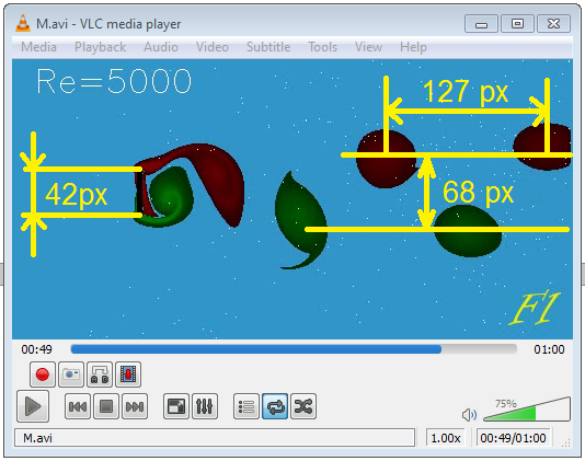
Fig. L9. Measuring the wake
Paint, and many other programs working with bitmap images, show the coordinates of the cursor in pixels. We used this feature to make the measurements shown. From the result one can see that if the height of the mirror is accepted as the unit of length, the wake height is H=68/42=1.62. (We round everything to 3 digits because it is surely enough, given how approximate the position of the vortices is.
Estimate the velocity in the wake. The fluid velocity inside the wake varies from particle to particle so, we need a measure of the average velocity in the wake. We will use the velocity of the vortices as such a measure. To obtain the velocity of the vortex, stop the movie in the player, and adjust the time so that the vortex edge just touches the right edge of the player screen, as shown in Fig.L10. Notice the time. Then move the time-slide until the next vortex comes to the same position near the edge, notice the time, and repeat it again. Figs.L10-L13 show the times for the sample video we are analyzing. The times are 49 s, 52 s, 56 s, and 59 s.
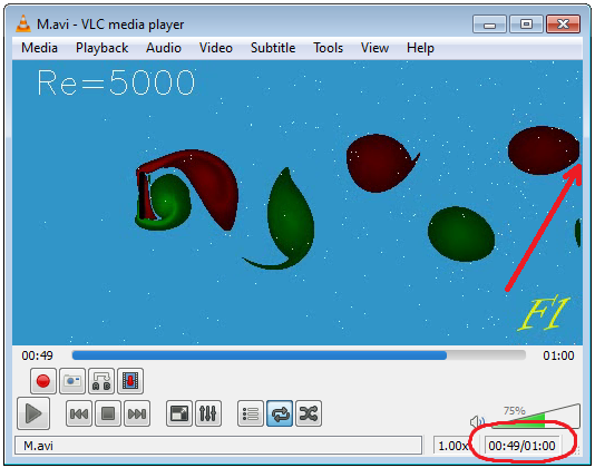
Fig.L10 The wake at the 49th second.
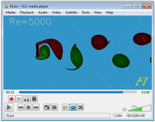
Fig.L11 The wake at the 52nd second.
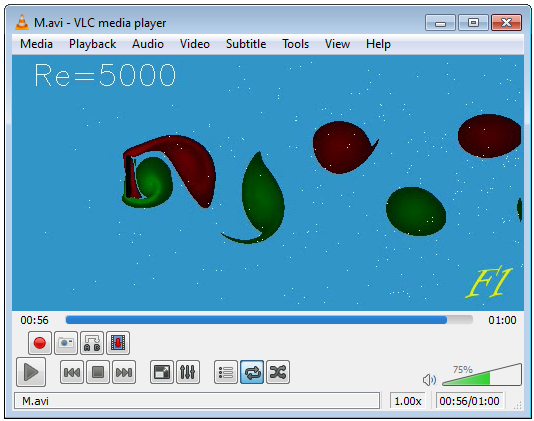
Fig.L12 The wake at the 56th second.
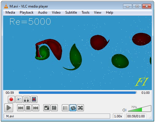
Fig.L13 The wake at the 59th second.
Estimate the distance between the vortices. In our Fig.L9 we got 127 pixels. Hence, the velocity of the vortices is 3×127/(59-49)=38.1px/s. Using several vortices improves the accuracy (think why).
The speed with which the mirror moves, or, in Flow Illustrator, the speed with which the fluid particles approach the mirror from upstream, is given by the formula hpic×dt×24px/s. In this formula hpic is the height of the video in pixels (for the standard test images we offered to download it is 256) and dt is the parameter set on the Flow Illustrator “Run Simulation” page”. Its default value is 0.01. This formula could be checked by measuring the speed of the snowflakes moving along the lower or upper edge of the video screen in the same way in which the velocity of the vortices was calculated. For the pictures of the standard size and at the default value of dt this gives 61.44 px/s.
In the frame of reference of the road, the mirror will be moving with the velocity 61.44px/s to the left, and the vortices will be also moving to the left, with the velocity 61.44-38.1=23.34 px/s. Hence, the average velocity in the wake will be 23.34/61.44=0.38 V. From the formula we derived earlier the fuel consumption is proportional to HU2. As compared with our first crude estimate, H turned out to be 1.62 times greater, but U turned out to be 0.38 of what we assumed in that calculation. Hence, a better estimate for the fuel consumption will be 1.62×0.382=0.234 of what we calculated earlier. It is, of course, very approximate anyway.
Now, estimate the relative reduction of the fuel consumption for your mirror, and compare it with what others people will get. Discuss.
The end of the lesson.